Biomedical Engineering Collaboration
In the Spring 2023 semester, our junior Product Design studio served as a Design Consultancy and collaborated with the senior Biomedical Engineering (BME) students to help them elevate their capstone projects. As a part of this project, I personally worked directly with one of the BME groups to bring their concept to life, so to speak, through CAD modeling, physical prototyping, and animation.
Each of the groups in the BME class had the opportunity to choose their own focus areas. The group I primarily worked with’s focus centered on adjustable leg rests that could be attached to wheelchairs, while the other group’s project was based on creating a 3D-printed Corpectomy Prosthesis.
Adjustable Wheelchair Leg Rests Group
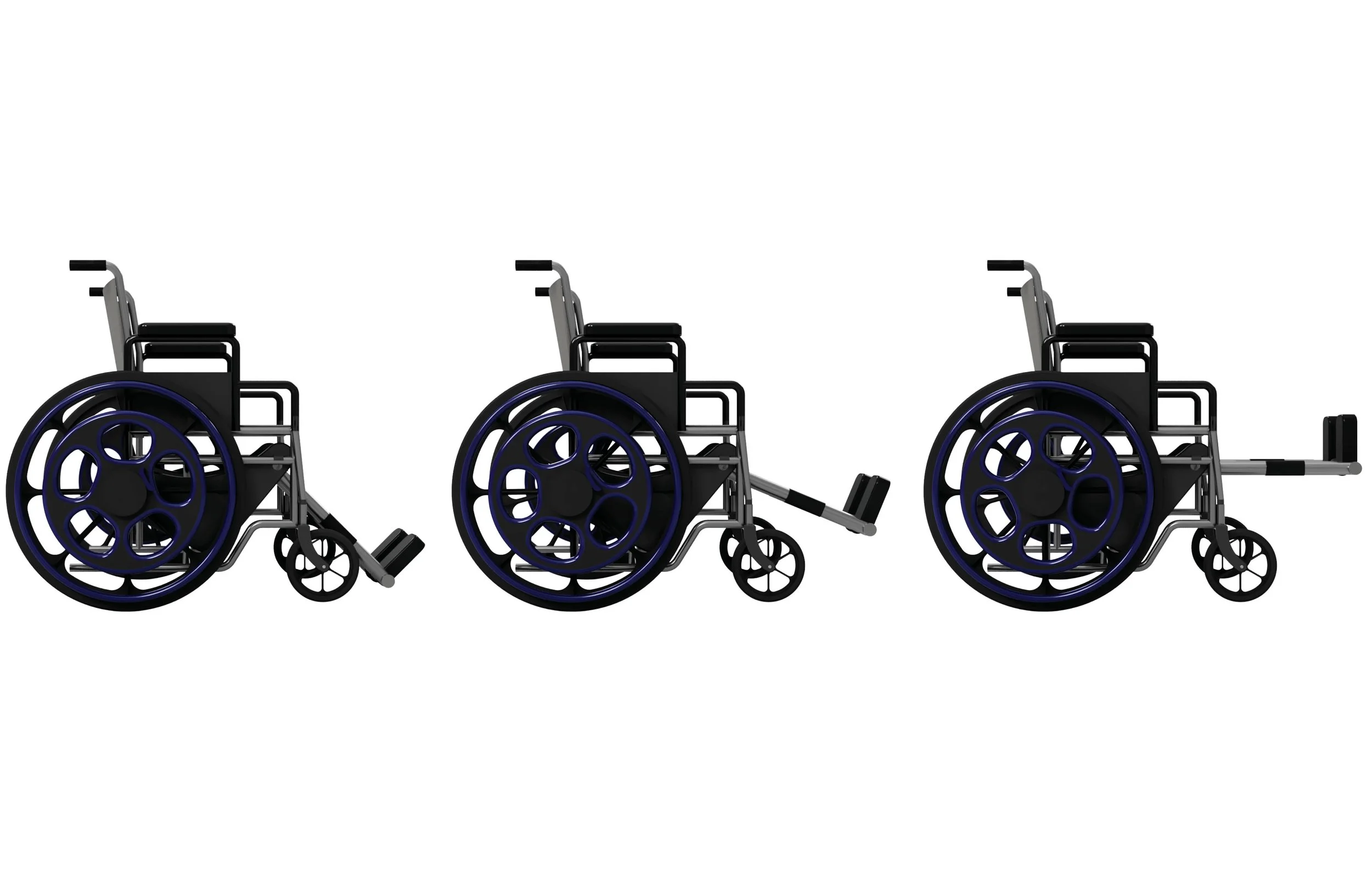
The BME group I had the opportunity to primarily work with looked to design an attachment for wheelchairs that would replace the standard leg/footrests with ones that could be raised and lowered for comfort.
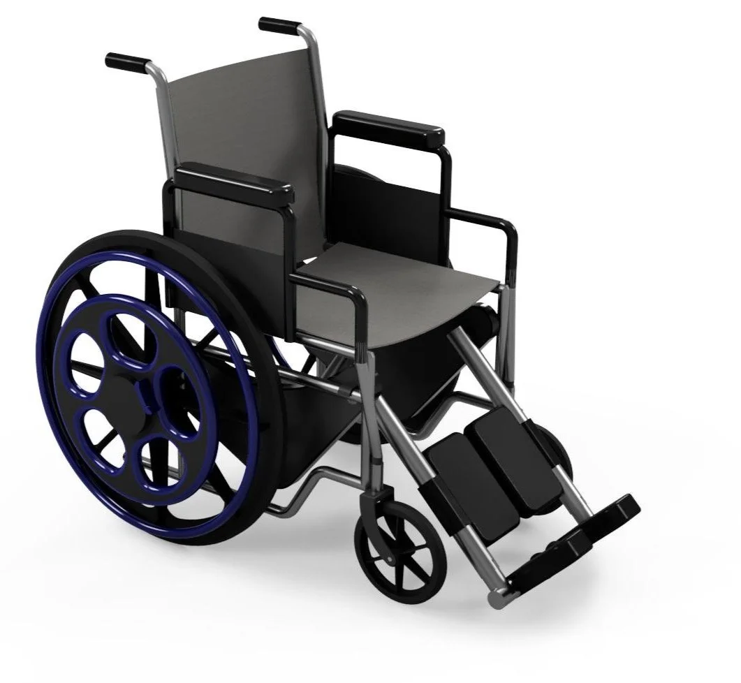
In regards to this group, my task was to take their initial engineering concept and elevate it into the form it might take if it were a shelf-ready product. Essentially, I was creating the future, market-ready version of their initial idea.
The barebones of their groups’ concept was attachable legs rests that could be raised and lowered. This meant I had the freedom to iterate on the raising and lowering mechanism and its physical interaction points. My goal was to design the system in a way that would provide a familiar and comfortable experience for the user when raising or lowering the leg rests.
Interface Iteration: Sketching
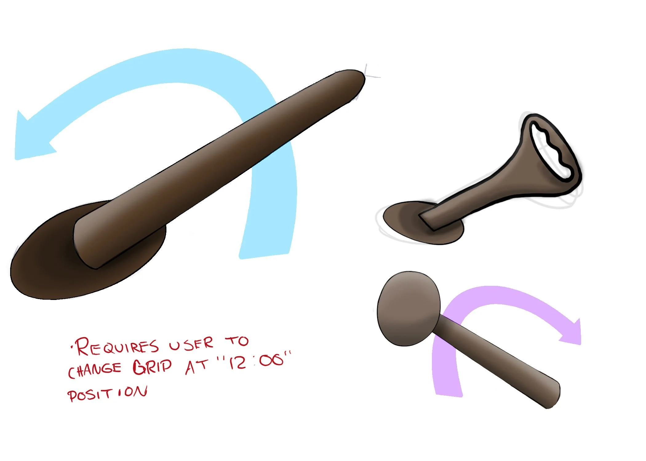
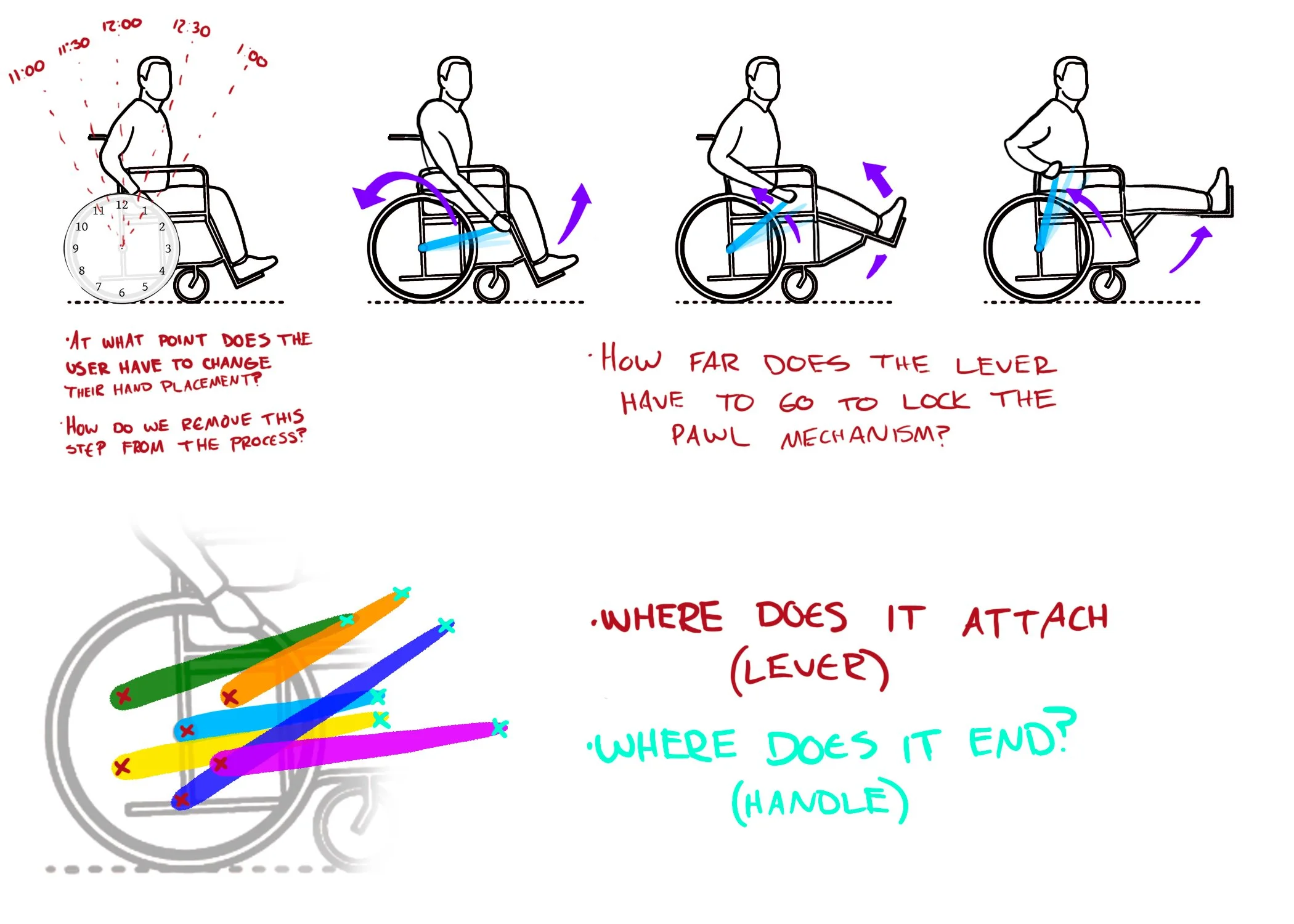
The first step I took was to iterate on the physical interface of the adjustment mechanism. This included handle type/form, along with its placement on the wheelchair in relation to the user and their reachability. In an attempt to create a familiar experience for the user, I modeled the early iterations after recliners, as they are also a seating device with a handle attachment used to raise and lower a leg rest.

Interface Iteration: Sketching
Continued iteration led to a new mechanism that could be used to adjust the leg rests. Rough sketches of different ways the mechanism could be adjusted along with the physical form of the mechanism and its features were used to explore varying adjustment methods.
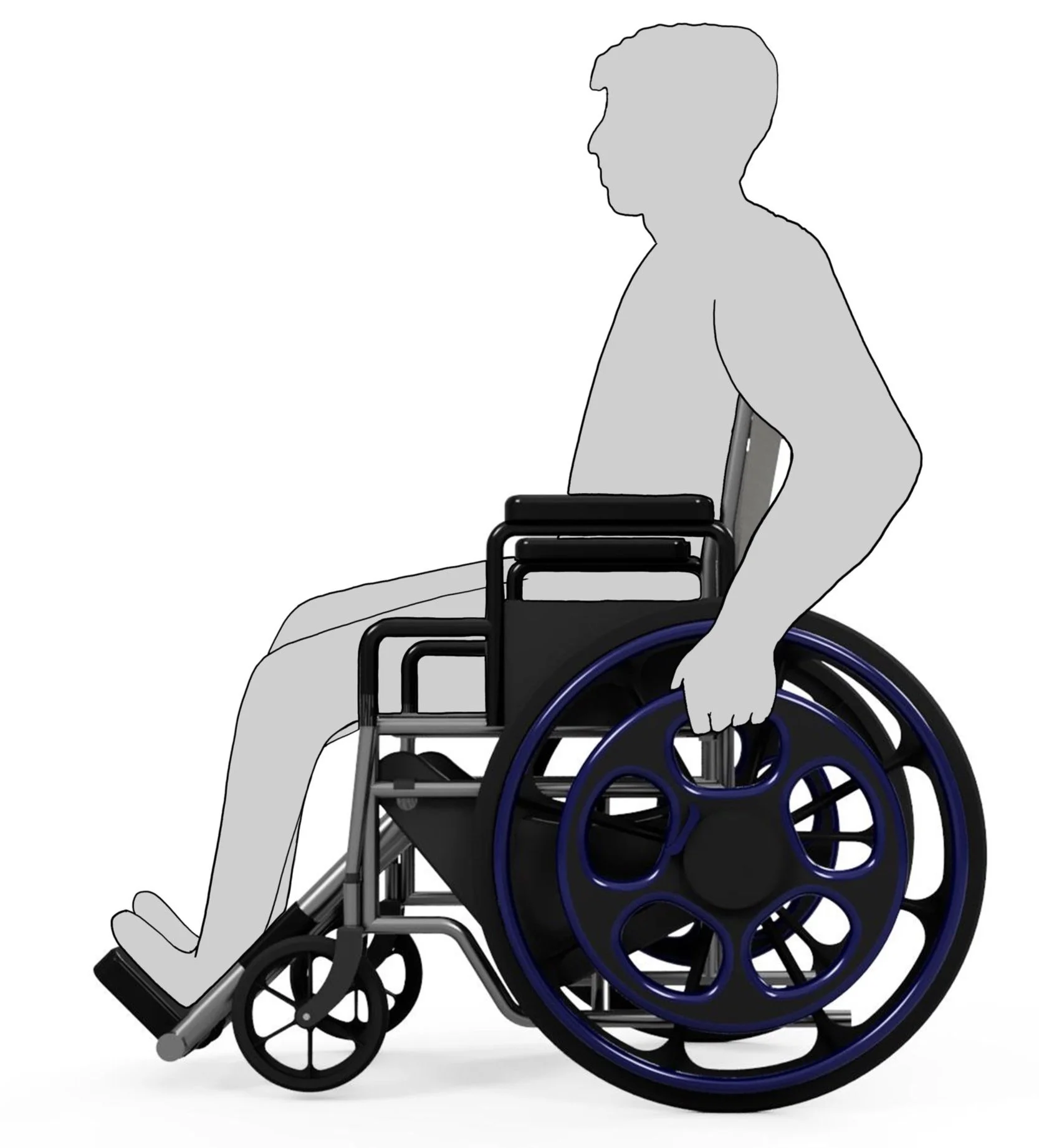
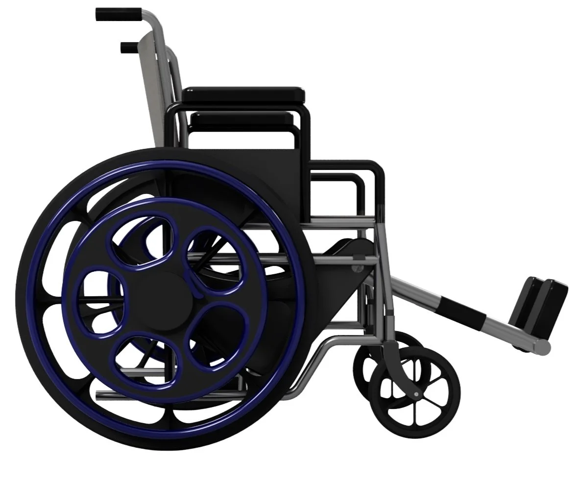
As to accomplish the goal of providing a familiar experience for the user, I decided to move forward with the concept of using an additional wheel to raise and lower the leg rests rather than a typical handle. This idea was dubbed the “Wheel Within a Wheel”.


Interface Iteration: Sketching
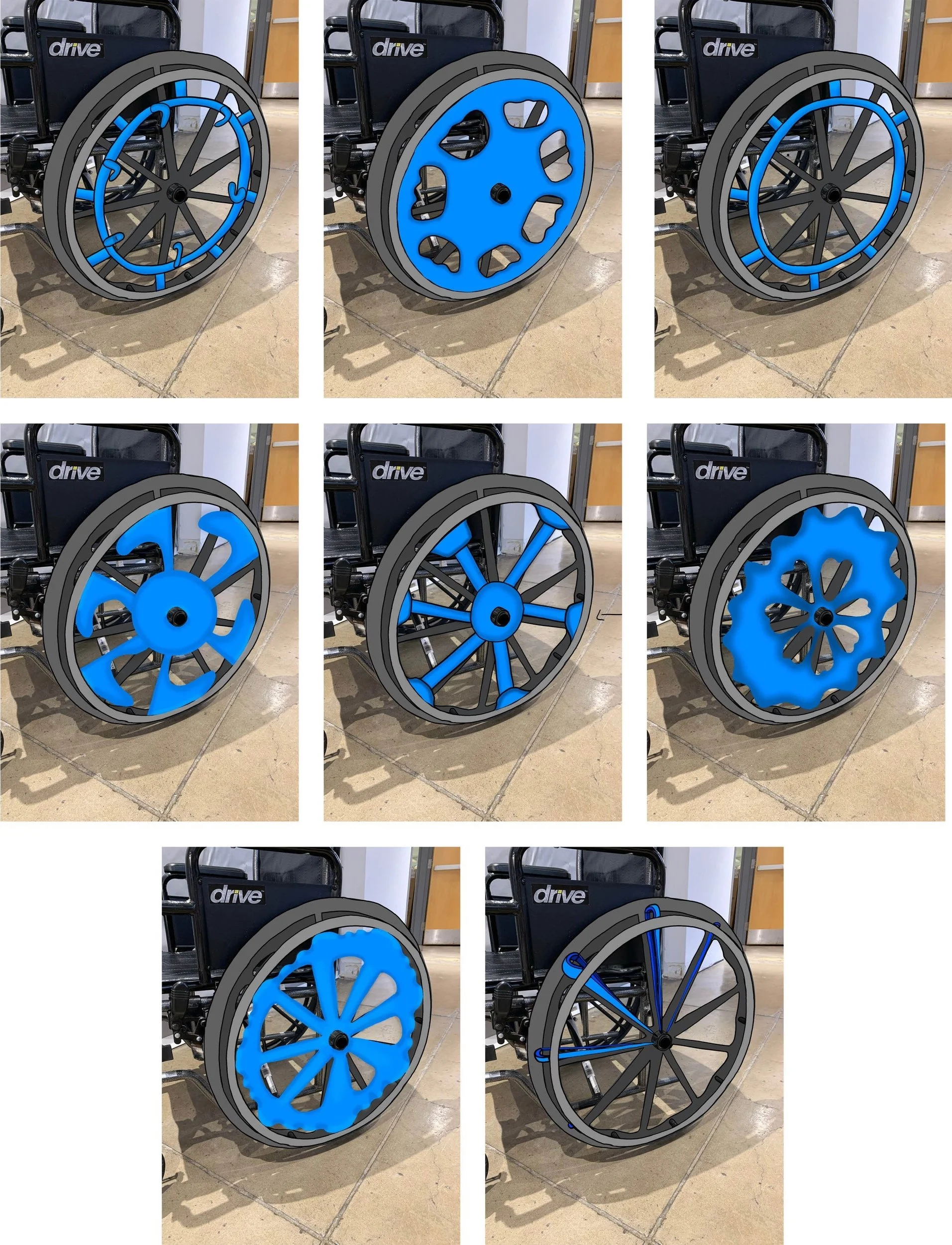
The next step was to iterate on the physical form the Wheel Within a Wheel (WWAW) could take. The form of this component was crucial to the overall success of the design, as it was the sole touchpoint the user would interact with when adjusting the leg rests. This form had to still aid in providing a familiar experience for the user, but had to contrast with the actual wheels and their handles to ensure the user wouldn’t confuse the two.
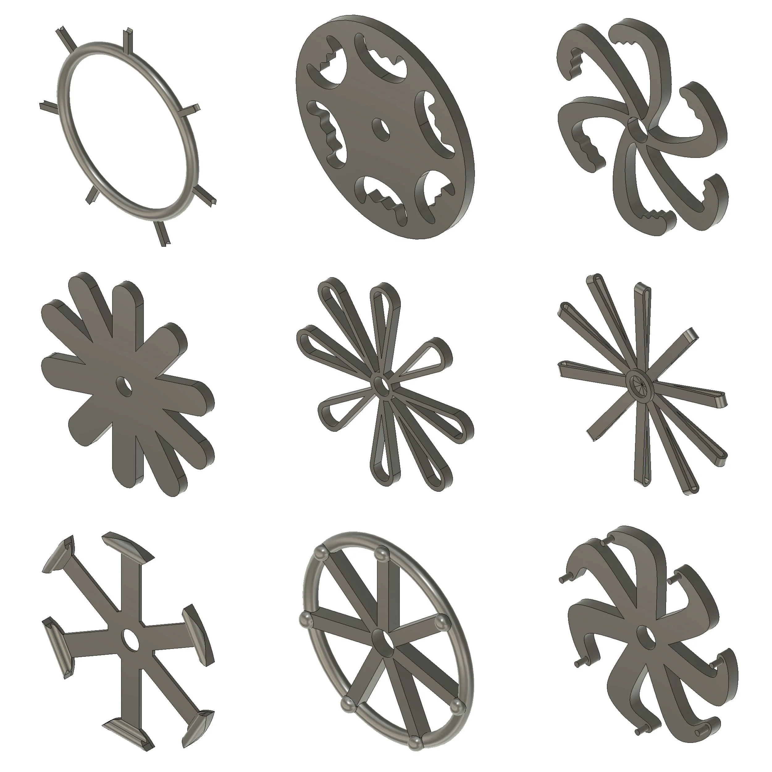
CAD Modeling
After sketching some initial ideas, I quickly modeled a few to further compare the current possibilities.
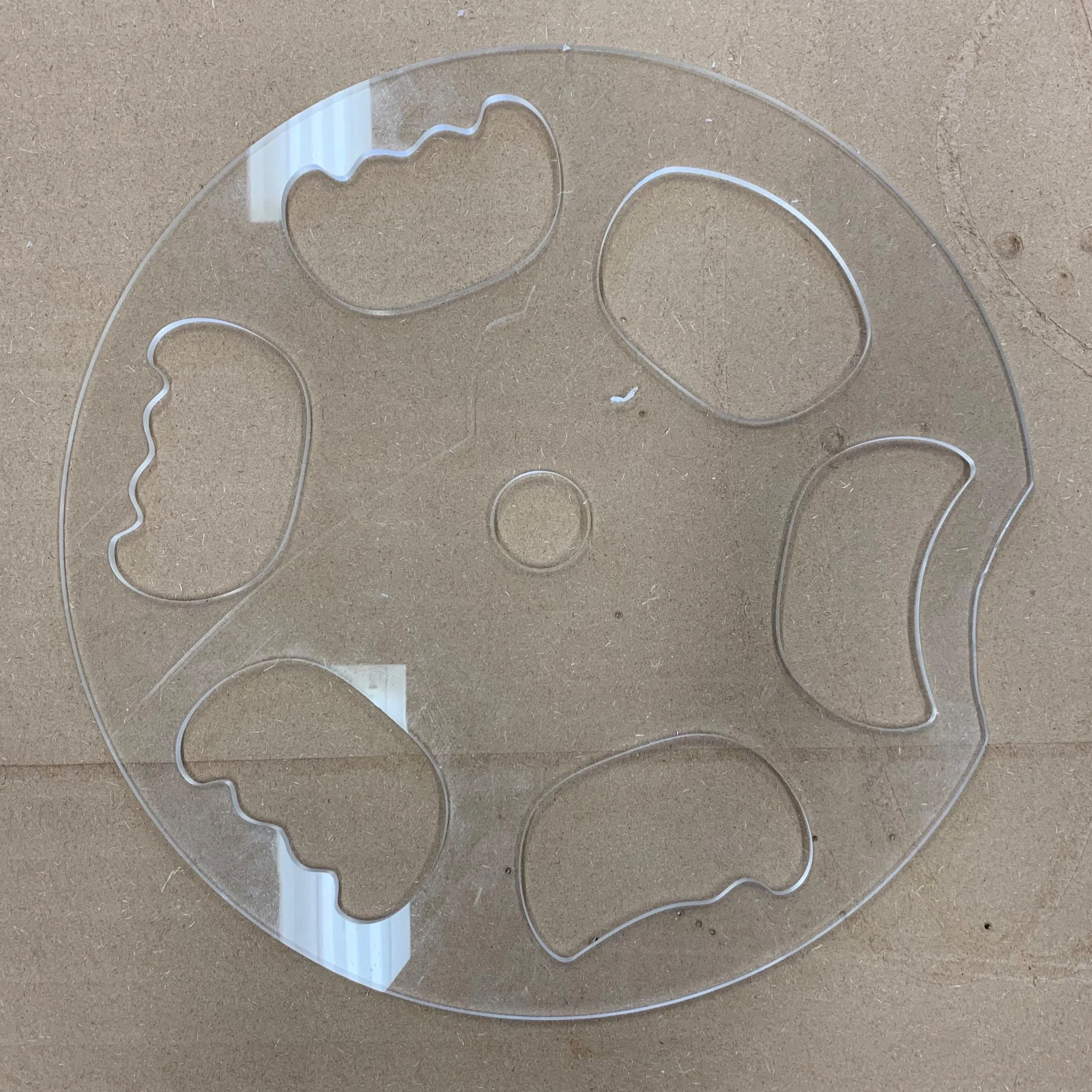
Physical Prototyping
The next step was to prototype the concepts. In order to do so, each model was cut from acrylic using a CNC. The goal here was to get a better sense of the scale of the WWAW, the comfort of the grip, and the interaction with the interface as a whole. The different prototypes were tested and voted on by peers from around the College of Design in conjunction with a popular model of wheelchair that was borrowed from a local business.

Physical Prototype Iteration/Selection
After many of the physical prototypes had been tested with various individuals, the most favorable forms were then combined into one final prototype to allow people to quickly test and differentiate between the designs. This allowed me to narrow down to one final form, which I could then use for the remainder of the project.


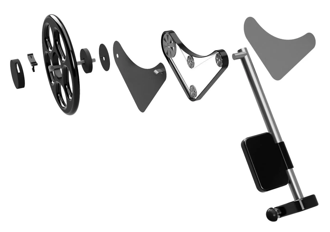
PAWL Mechanism
In order to allow the leg rests to be raised and lowered without falling out of place afterward, a PAWL mechanism was utilized.
Note: I did not design the PAWL mechanism. It was mocked up by a classmate and I then used the CAD model in the rest of the design for visualization purposes.

Key:
1. Anvil - also acts as the axel that holds the current wheels as well as the added ones
2. Pawl Mechanism - allows the footrests to lock in place as they’re raised or lowered
3. Pawl Switch - switches the direction the wheel can be rotated with the pawl mechanism still locking
4. Pulley System - mechanical connection between the wheel/axel and the footrests
5. Footrest - component that is manipulated by the rotation of the wheel